
Why hydrogen reducing skids cannot copy natural gas skids
Most mistakes in hydrogen pressure-reducing equipment are not a wrong model number; they come from copying a natural-gas skid straight across. Both gases are flammable and both need reducing, yet the property gap forces five parts of the design to be rebuilt: throttling warms the gas instead of cooling it, the materials face hydrogen embrittlement, sealing and permeation demand far more, explosion protection and leak detection follow different logic, and metering has to be settled on energy rather than volume.
This article sets out those five differences against current standards and published test data, and closes with an executable selection checklist. The figures are order-of-magnitude estimates from standard properties and typical duty; every project still has to be checked against its design documents and actual duty.
Most mistakes in hydrogen pressure-reducing equipment are not a wrong model number; they come from copying a natural-gas skid straight across. Both gases are flammable and both need reducing, yet the property gap forces five parts of the design to be rebuilt: throttling warms the gas instead of cooling it, the materials face hydrogen embrittlement, sealing and permeation demand far more, explosion protection and leak detection follow different logic, and metering has to be settled on energy rather than volume.
1. Start with six property numbers: the source of every difference
- Density at standard conditions: hydrogen 0.0899 kg/Nm³, natural gas (mainly methane) about 0.717 kg/Nm³ — roughly eight times higher.
- Lower volumetric calorific value: hydrogen about 10.8 MJ/Nm³, natural gas about 35.9 MJ/Nm³ — about one third.
- Flammable limits in air (volume fraction): hydrogen 4%–75%, natural gas about 5%–15%.
- Minimum ignition energy: hydrogen 0.017–0.02 mJ, natural gas about 0.28–0.3 mJ — about fifteen times higher.
- Diffusion coefficient in air: hydrogen about 0.61 cm²/s, natural gas about 0.16 cm²/s — hydrogen diffuses about four times faster.
- Joule–Thomson coefficient: negative for hydrogen (throttling raises the temperature), positive for natural gas (throttling lowers it).
Sources: GB/T 29729—2022 Basic requirements for the safety of hydrogen systems, Annexes B and C and Clause 5.2.1; GB 4962—2008 Safety technical regulations for the use of hydrogen, Annex A.
The first five decide safety and metering; the last decides thermal design — and it is the last one that people copying a skid overlook most often.
2. First change: after throttling the gas warms, it does not cool
The entire freeze-protection logic of a natural-gas skid rests on “throttling must cool”: 25 MPa down to 0.4 MPa drops the temperature by seventy or eighty kelvin, so heat has to be added or the valve trim ices up. Hydrogen is the opposite: at ambient conditions its Joule–Thomson coefficient is negative, so the temperature rises after throttling expansion.
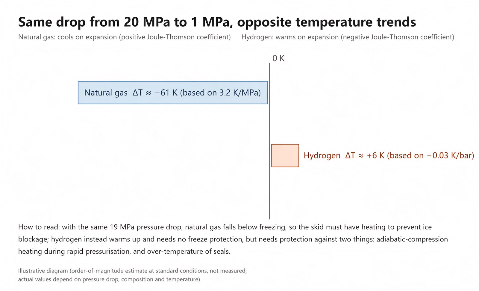
Figure 1 — Same drop from 20 MPa to 1 MPa, opposite temperature trends (illustrative, not measured)
Estimated at about −0.03 K/bar, a drop from 20 MPa to 1 MPa gives roughly a 6 K rise. The number is small, but the direction is reversed, and it carries three direct conclusions:
- No need to copy the heating section or the ice-blockage design. Extra heaters and heat tracing only add leak points and failure points.
- A new ignition source appears: adiabatic compression. During rapid pressurisation the hydrogen in the downstream cavity is compressed and its temperature climbs sharply, enough to self-ignite in an oxygen-rich atmosphere. Valves must therefore be opened slowly and pressurisation staged; this is far less prominent in natural gas.
- The temperature margin of the seals has to be recalculated. Throttling heat-up on top of summer ambient can bring non-metallic seals on the low-pressure end close to their allowable temperature sooner than in natural-gas duty.
Hydrogen-blended projects need one more check: blending lowers the Joule–Thomson coefficient of the mixture. One published study reports that at atmospheric pressure and 283 K, raising the hydrogen fraction from 0 to 30% lowers the coefficient from 5.42 K/MPa to 3.04 K/MPa. In other words, blended gas still cools and can still ice up, but the heater duty cannot be sized on the pure natural-gas coefficient — it must be recalculated for the actual blend.
3. Second change: the material is not “stainless is enough”, it has to resist embrittlement
Hydrogen embrittlement is hydrogen atoms diffusing into the metal, gathering at stress concentrations and accelerating crack initiation and growth. It shows up as delayed fracture: the part is sound when installed and fails suddenly after running for a while. The harder and stronger the steel, the more sensitive it is, which is why the standards cap hardness for hydrogen service.
Materials cannot be chosen by habit. GB/T 29729—2022 Annex D lists the metals commonly used in hydrogen service, including austenitic stainless steels such as 316L (S31603) and S31608, 6061 aluminium alloy, and line-pipe steels such as X42 and X52. SY/T 7820—2024 Design code for hydrogen pipeline engineering sets requirements for line-pipe materials in Chapter 4 and for pipeline components (valves, seals) in Clause 4.3. In practice:
- valve bodies, trim and fittings are mainly austenitic stainless steel, and both castings and forgings need a basis for hydrogen service;
- high-strength steels, hardened parts and spring steels stay out of the hydrogen side;
- weld joints have hardness controlled, with post-weld heat treatment and re-inspection where necessary;
- non-metallic parts are listed separately (see the next section) and never bundled into one material table with the metal parts.
To judge whether a supplier has really worked in hydrogen, do not read the material certificate; ask for two things: a hydrogen compatibility test report (the GB/T 34542 series) and operating records on the same medium. A “316 stainless skid” that can produce neither is, in essence, still a natural-gas skid.
4. Third change: sealing and permeation are the first things to fail
A hydrogen molecule is only 2 g/mol, so its permeation and leak capability is far beyond methane. The same packing arrangement that holds on natural gas will leak noticeably more on hydrogen. Three hard requirements on material and structure:
- Non-metallic seals are mainly PTFE, PEEK, PCTFE and flexible graphite, with metal seals where necessary. Ordinary nitrile rubbers (NBR/HNBR) are not reliable under high-pressure hydrogen cycling: in published tests HNBR specimens showed cracks and defects on the cross-section after high-pressure hydrogen cycling, so such materials should not be the primary seal on the hydrogen side.
- Stem packing should preferably be live-loaded, to compensate the preload lost to permeation and wear; at low pressure a packless diaphragm or bellows arrangement removes the stem leak path at the root.
- Leak-testing method and frequency have to be listed separately: helium leak testing before commissioning (vacuum or sniffer method), hand-held hydrogen detectors in service covering flanges, packing, threaded joints and vent outlets, and a repeat pass after any maintenance. Hydrogen diffuses upward fast, so the leak points must include the ceiling space and the top of the piping, not just the low points as on natural gas.
The leak-rate figure belongs in the contract, not in “we will sniff for it at acceptance”.
5. Fourth change: the explosion-protection logic differs, detector positions have to be rearranged
The flammable range of hydrogen is 4%–75% by volume, per GB/T 29729—2022 Clause 5.2.1 and GB 4962—2008 Annex A Clause A.3; the minimum ignition energy is 0.017–0.02 mJ, about one fifteenth that of natural gas. Those two numbers mean the smallest static discharge can ignite it, and a leak reaches a flammable concentration quickly.
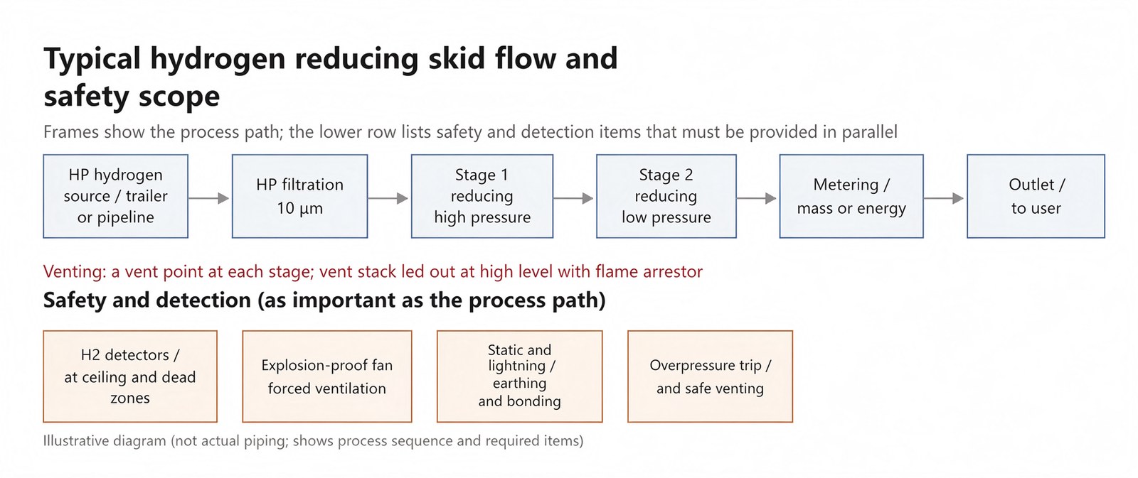
Figure 2 — Typical hydrogen reducing skid flow and safety scope (illustrative, not actual piping)
One detail is often written wrong: 18.3%–59% is the detonation range of hydrogen, not its explosion limit. Mixing the two yields the false conclusion that hydrogen is only dangerous above 18%. Design briefings and training must keep them apart: the flammable (explosive) limits of 4%–75% govern leak alarms and area classification; the detonation range is used to assess extreme consequences inside confined spaces and piping.
At the configuration level the differences from a natural-gas skid concentrate in four points: detectors placed at the ceiling and in dead zones (and covering buried piping above ground), forced ventilation interlocked with emergency exhaust, system-wide static earthing and bonding, and vent stacks led out at high level with flame-arresting elements. The hydrogen flame is nearly invisible and radiates little heat, so visual discovery and heat detection are both late; critical areas should have UV/IR flame detection.
Commissioning and maintenance purging cannot be copied from natural gas either: inert-gas purge until the hydrogen content in the pipe falls below the safe value, with both oxygen and hydrogen measured, before any hot work or gas admission.
6. Fifth change: meter on energy, not on volume alone
One normal cubic metre of hydrogen carries about one third the heat of natural gas. The user buys heat, not volume, and that settles three things:
- Pipe size and flow cannot be copied. To carry the same heat load, the volumetric flow of hydrogen is about three times that of natural gas, so bore, velocity and pressure drop all have to be recalculated; excessive velocity also brings static and noise problems.
- The meter has to be the right type. With hydrogen’s low density, differential-pressure (orifice) meters lose accuracy at the low end; Coriolis mass meters and ultrasonic meters suit billing better, and purity, temperature and pressure compensation must be complete.
- The settlement basis must be explicit. Billing by mass (kg) or by energy (calorific value × volume) directly affects meter selection and contract terms; leave it vague and reconciliation becomes a running argument.
7. The five most common mistakes
- Copying the whole heating section from a natural-gas skid. Hydrogen needs no ice protection; the extra heater only adds leak points and energy cost.
- A 316 valve body with ordinary rubber seals. Leaks usually start at the packing and O-rings; a handsome material table does not mean it holds.
- Sizing pipe on volumetric flow. The volumetric calorific value is one third, so the user’s demand has to be converted to heat load first.
- Carrying over natural-gas detector positions and counts. Hydrogen diffuses faster and gathers at the ceiling; the layout has to be assessed separately.
- Carrying over natural-gas leak methods and intervals. Helium testing, hydrogen detectors and re-test frequency all belong in the technical agreement as separate items.
8. Selection checklist: twelve items, one by one
- Inlet pressure range and fluctuation (including output check at minimum inlet pressure)
- Outlet pressure and regulating accuracy
- Maximum and minimum flow, and turndown ratio
- Medium: pure hydrogen or blend ratio, purity requirement
- Temperature: limits of medium and ambient temperature
- Material: grade, hardness cap, hydrogen compatibility test report
- Sealing: non-metallic grade, packing structure, metal-seated locations
- Leak testing: method and leak-rate figure, re-test interval
- Explosion protection: area classification, equipment protection level, earthing requirements
- Detectors and interlocks: positions, alarm values, trip logic
- Purging and venting: purge medium, end-point criteria, vent stack routing
- Metering: meter type, compensation method, settlement basis (mass or energy)
Conclusion
A hydrogen reducing skid and a natural-gas reducing skid can look very much alike, while their internal logic differs almost everywhere. Whether a unit is genuinely designed for hydrogen is not decided by the “H2” on the nameplate; look at four things: a material and compatibility basis for hydrogen service, a hydrogen-specific sealing system, leak detection and detectors re-laid out for hydrogen, and metering settled on energy.
Want a printable Hydrogen Reducing Skid Selection Checklist (twelve items to fill in and hand straight to a supplier)? Leave a message or send a DM and we will send it over.
Property data in this article are cited from GB/T 29729—2022 and GB 4962—2008; material and pipeline-component requirements from SY/T 7820—2024 and the GB/T 34542 series. The figures are order-of-magnitude estimates from standard properties and typical duty; a specific project is settled against its design documents, gas analysis and duty, and the standard clauses in force are authoritative.
For hydrogen equipment, see hydrogen equipment; for the regulating skids used on natural gas and CNG, see CNG reducing skids.
Written by the Tairan engineering team from project records and standard documents. Please cite the source when quoting.